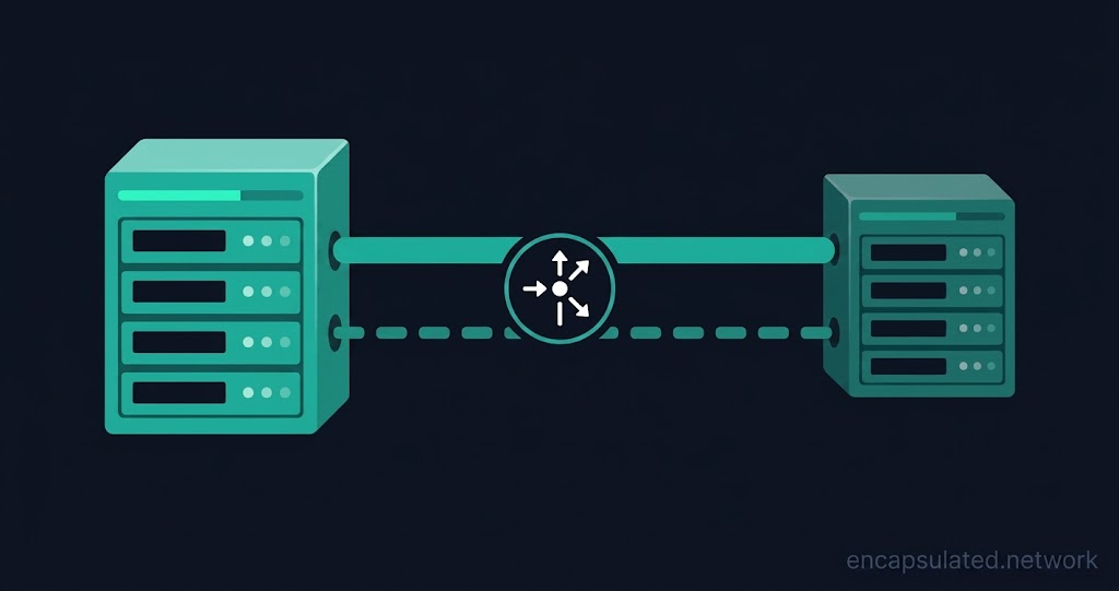
A site-to-site VPN is an encrypted connection between two network gateways that permanently links two separate networks across the public internet, allowing devices at each location to communicate as if they share one private network.
No VPN client software runs on the individual devices inside either network. The gateways handle all encryption, decryption, and routing; traffic between the two networks flows through the tunnel automatically, transparent to every device on either side.
TL;DR
- A site-to-site VPN permanently connects two separate networks through encrypted gateways; every device at each location can reach the other network without any VPN client software installed. The gateways handle all encryption and routing transparently.
- Two models exist: intranet (same organisation, headquarters to branch) and extranet (separate organisations, with access control lists limiting what the remote side can reach). Neither model requires individual users to take any action; the tunnel is available continuously (most platforms hold it up or bring it up automatically on the first packet).
- IPsec with IKEv2 is the standard. The gateways negotiate algorithms and establish shared keys, then authenticate each other, before any data flows. When setup fails, different problems surface at predictable points in the exchange sequence.
- The tunnel protects only traffic that crosses it between the two gateways. Traffic within each network, traffic that bypasses the gateway, and the broad implicit access the tunnel grants to the remote network all fall outside its protection scope.
Other names for site-to-site VPN
A site-to-site VPN is one of three VPN product types, alongside personal VPNs for individual privacy and remote-access VPNs that connect single devices to a network; see what a VPN is for all three. The architecture goes by several names: LAN-to-LAN VPN and L2L VPN (common in Cisco documentation), gateway-to-gateway VPN (the term used in NIST SP 800-77 Rev. 1), network-to-network VPN, and branch-office VPN all refer to the same design. “Site 2 site VPN” drops the hyphens but means the same thing.
How a site-to-site VPN works
The gateway model
Each location has a gateway device: a router, firewall, or dedicated VPN appliance. All traffic destined for the remote network is intercepted by the local gateway, encrypted, and forwarded through the tunnel. The remote gateway decrypts it and delivers it to the destination device. Devices at each location can reach each other as if on one private network; the tunnel joins the sites at the routing layer, not the data-link layer. Broadcast-based discovery mechanisms (Windows network browsing, mDNS/Bonjour, printer auto-discovery) do not cross a routed tunnel at all. Carrying them between sites requires separate infrastructure: an mDNS reflector, DNS-SD, WINS, or a layer-2 bridged tunnel.
The tunnel is built using packet encapsulation; for how that works in full, see what a VPN tunnel is.

A worked example: headquarters to branch office
A company runs its headquarters network on 10.1.0.0/24 and its branch office on 10.2.0.0/24, joined by a site-to-site VPN. A branch laptop at 10.2.0.45 opens a file share on an HQ server at 10.1.0.80.
The branch laptop sends a standard IP packet addressed to 10.1.0.80. The branch gateway sees the destination falls in 10.1.0.0/24, which its routing table points at the VPN tunnel interface. The gateway encrypts the packet and forwards it to the HQ gateway across the public internet. The HQ gateway decrypts it and delivers it to 10.1.0.80 on the HQ LAN. The file server responds; the HQ gateway encrypts that response and returns it through the tunnel; the branch gateway decrypts it and the laptop receives it. Neither the laptop nor the file server knows a VPN is in use.
What does not cross the tunnel: broadcast traffic. Network browsing and printer discovery that rely on link-layer broadcasts stay local; carrying them cross-site requires additional infrastructure such as an mDNS reflector or DNS-SD. Cross-site name resolution requires a DNS server reachable across the tunnel, or DNS conditional forwarding configured to direct queries for one site’s hostnames toward the other site’s DNS resolver.
IKEv2 setup: IKE_SA_INIT, IKE_AUTH and CREATE_CHILD_SA
IKEv2 establishes the connection in two exchanges, four messages in the common case.
IKE_SA_INIT: the two gateways negotiate cryptographic algorithms, exchange nonces, and perform the Diffie-Hellman key exchange. The output is an encrypted, integrity-protected control channel: the IKE Security Association (IKE SA), which protects everything that follows. It is not yet authenticated: neither gateway has proved its identity.
IKE_AUTH: protected by the keys derived in IKE_SA_INIT, this exchange verifies both gateways’ identities and establishes the first Child SA: the IPsec Security Association that carries site-to-site data traffic. The IKE SA is only fully established once IKE_AUTH completes. In the common two-gateway deployment, these four messages complete the entire setup sequence.
CREATE_CHILD_SA runs afterwards only: to add further Child SAs or to rekey existing ones as their lifetimes expire. It does not run during initial setup.
Different configuration problems surface at different points in this sequence, which makes site-to-site failures diagnosable. If the two gateways share no algorithm in common for the IKE SA, the responder returns NO_PROPOSAL_CHOSEN and IKE_SA_INIT produces no IKE SA. A Diffie-Hellman group mismatch on its own is not fatal: if the initiator proposes a group the responder does not support, the responder replies with INVALID_KE_PAYLOAD naming the group it wants, and the initiator retries IKE_SA_INIT with that group; only when the two sides share no group at all does the exchange fail. Authentication failures (wrong pre-shared key, untrusted certificate, unexpected identity) surface in IKE_AUTH, not IKE_SA_INIT. Child SA failures (mismatched ESP proposals or traffic selectors that cannot be reconciled) surface in IKE_AUTH or in a later CREATE_CHILD_SA; when a Child SA fails, the IKE SA remains established and no data tunnel exists behind it. See how a VPN establishes its connection for the full sequence.
Intranet vs. extranet site-to-site VPN
Intranet site-to-site VPN
An intranet site-to-site VPN connects locations within the same organisation. All connected sites share full access to designated shared resources: file servers, internal applications, and databases appear on both sides as if part of one private network. Traffic flows through the tunnel with no distinction by user, application, or device. Headquarters-to-branch connectivity is the canonical deployment; on-premises-to-cloud VPC connectivity is its modern equivalent.
Extranet site-to-site VPN
An extranet site-to-site VPN connects separate organisations. The defining difference from an intranet deployment is deliberate segmentation: access control lists and firewall policies on each gateway define exactly which subnets and services the remote organisation can reach. The tunnel grants access to a defined zone, not the full internal network.
Use cases: a manufacturer granting a supplier read access to a specific inventory API while blocking all other subnets; two merging companies sharing particular datasets while keeping their directories separate; an audit firm accessing defined compliance logs under a time-limited connection.
A common design recommendation is to land extranet tunnels in a DMZ or dedicated partner zone rather than directly on the internal LAN. Firewall policy between that zone and the LAN then limits what a compromised partner network can reach.
Advantages and limitations of a site-to-site VPN
Advantages
No user involvement. The tunnel runs without any user action. Most platforms hold the tunnel up continuously or bring it up automatically on the first packet; no individual user needs to install software or authenticate to a VPN.
Runs on existing circuits. A site-to-site VPN uses the sites’ existing internet connections rather than a dedicated WAN circuit. Where a site has no suitable circuit, or the tunnel would saturate it, bandwidth still needs to be provisioned.
Standards-based interoperability. IKEv2/IPsec is an open standard; gateways from different vendors generally interoperate when their policies overlap, so on-premises appliances and cloud managed gateways can join the same tunnel.
High availability. A single-tunnel deployment loses connectivity while a failure is detected and SAs are renegotiated. Dual tunnels with liveness detection reduce that to a routing change, with traffic resuming as soon as BGP converges on the secondary path.
Limitations and what it does not protect
No performance guarantee. Traffic crosses the public internet, which carries no SLA on latency, jitter, or packet loss between gateways.
Per-site bilateral configuration. Each new site pair adds a tunnel to configure and maintain. The configuration burden grows with site count; at many sites, SD-WAN or a hub-and-spoke architecture reduces the overhead.
IP address planning constraint. Non-overlapping subnets must be agreed before deployment. Renumbering an operational network is operationally severe.
No protection for roaming users. A site-to-site VPN connects fixed locations; roaming employees are outside its protection scope.
Traffic within each network. The tunnel’s encryption covers only the path between the two gateways. Traffic moving between devices on the same side receives no protection from it.
Traffic that bypasses the gateway. A device connecting directly to the internet from behind the gateway receives no tunnel protection.
A compromised gateway. The gateway concentrates trust for every device behind it. A compromised gateway gives an attacker access to the tunnel from inside; gateway hardening and a current patching cadence are the relevant controls.
Implicit broad access. A site-to-site VPN grants the remote network broad access to local resources; every device behind the remote gateway can reach every local device that routing and firewall policy allows. There is no per-user, per-application, or per-device verification. Zero Trust Network Access architectures replace this broad grant with per-connection verification.
What you need to deploy a site-to-site VPN
Prerequisites
- A gateway device at each location. A router, firewall, or dedicated VPN appliance with IKEv2/IPsec capability. In cloud environments the gateway is a managed virtual resource: AWS Virtual Private Gateway or Transit Gateway, Azure VPN Gateway, or GCP Cloud VPN. The gateway handles all encryption, decryption, and tunnel routing.
- A reachable public address at each gateway. Both gateways must be reachable from the internet. A static public IP is the standard path. IKEv2 includes built-in NAT traversal for gateways sitting behind a NAT device. Some configurations (certificate-based authentication on AWS, for example) remove the static-IP requirement on one or both sides; confirm the specific gateway’s documentation before planning.
- Non-overlapping IP address ranges on each side. If both sites use the same subnet, the routing table cannot distinguish local from remote traffic. IP address planning must precede deployment; cloud gateways typically check for this condition and reject overlapping ranges at configuration time, though on-premises appliances may not.
- Overlapping IKEv2 policy on both gateways. For the IKE SA: at least one encryption algorithm, PRF and Diffie-Hellman group in common; when using a non-AEAD cipher, also a matching integrity algorithm (AEAD ciphers such as AES-256-GCM carry integrity themselves and are proposed without a separate integrity transform). For the Child SA: at least one ESP proposal in common and traffic selectors that can be reconciled. Each side needs credentials the other accepts: the same pre-shared key, or a certificate the peer’s trust anchor validates. SA lifetimes are local policy on each gateway and do not have to match; IKEv2 does not negotiate them (RFC 7296 §2.8).
Ports and protocols to allow between the gateways
Three protocol paths must be permitted between the two gateways’ public IP addresses. These rules are scoped to the peer gateway’s public IP, not opened to any source.
| Protocol / port | Purpose | When required |
|---|---|---|
| UDP 500 | IKE negotiation | Always |
| UDP 4500 | IKE and ESP when NAT traversal is in use | Always advisable: NAT presence is detected during IKE_SA_INIT, and some implementations default to UDP encapsulation on port 4500 even when no NAT is detected, because some middleboxes pass only TCP and UDP. A rule admitting only port 500 breaks those tunnels |
| IP protocol 50 (ESP) | Encrypted tunnel data | When NAT traversal is not in use (protocol number, not a TCP/UDP port) |
AH (IP protocol 51) is the alternative to ESP, not a supplement. ESP provides encryption and integrity protection; AH authenticates without encrypting and is incompatible with NAT. A standard deployment needs only IP protocol 50 (ESP); protocol 51 is not required.
When subnets overlap
In merger and acquisition scenarios, partner extranet links, or environments where both sites use default RFC 1918 ranges, NAT is the engineering solution. Two approaches exist. The first: each gateway maps its real subnet to a unique virtual range for tunnel-bound traffic; the remote side sees virtual addresses rather than the overlapping real subnet, and both gateways must be reconfigured. The second: Twice NAT (RFC 2663 §4.3) on a single gateway applies both source and destination address translation simultaneously, which suits situations where only one side can make configuration changes.
Security: IPsec, authentication and algorithms
ESP, and why AH is rarely used
ESP (Encapsulating Security Payload, RFC 4303, IP protocol 50) normally provides both encryption and integrity protection; the exact service set is chosen when the SA is negotiated. It is the industry standard for site-to-site VPN. IPsec in tunnel mode encrypts the entire original IP packet and adds a new outer IP header, hiding the original source and destination addresses from every intermediate node. ESP’s integrity check covers the ESP-protected portion of the packet, not the outer IP header.
AH (Authentication Header, RFC 4302, IP protocol 51) provides data integrity, origin authentication, and anti-replay protection, but no encryption. Its integrity check covers header fields that must not change in transit, including the source and destination IP addresses; any NAT device that rewrites those addresses invalidates the check. AH is incompatible with NAT and rarely used in practice.
Pre-shared keys vs. certificates
Pre-shared keys (PSK) are a shared secret configured on both gateways. Configuration overhead is low for a two-site deployment with stable membership. The weakness is operational scale: each site pair requires a unique PSK, rotating a compromised key requires coordinated changes on both gateways simultaneously, and a single shared PSK across all pairs creates a wide blast radius on compromise.
Certificate-based authentication uses a PKI: each gateway holds a private key and presents a certificate signed by a common Certificate Authority. The CA verifies identity; neither gateway needs to share a secret directly. Certificates become increasingly preferable as site count grows, or wherever gateways are managed by separate teams. Certificates require a functioning CA and a lifecycle management process. Platform support varies: AWS supports certificate-based authentication via AWS Private CA; GCP Cloud VPN supports pre-shared keys only.
Cipher suite and DH group guidance
For new deployments: AES-256-GCM for encryption (an AEAD cipher providing confidentiality and authentication in a single operation), SHA-256 or SHA-384 for the PRF, and DH group 14 (2048-bit MODP) at minimum. Groups 19 to 21 (256 to 521-bit elliptic curve) are preferred for deployments expected to run beyond five years.
When using a non-AEAD cipher such as AES-CBC, pair it with HMAC-SHA-256 or stronger for integrity; no separate integrity algorithm is needed with AES-256-GCM. Avoid DES, 3DES, MD5, SHA-1, and weak DH groups. DH group 1 carries MUST NOT status and is formally deprecated per RFC 8247. DH groups 2 and 5 carry SHOULD NOT status: not formally deprecated, but no longer appropriate for new deployments. All three persist as misconfiguration risks on older hardware with weak defaults.
IKEv1: why it was deprecated and why it persists
IKEv1 was formally deprecated by RFC 9395 in April 2023, which moved the IKEv1 specification set (RFCs 2407, 2408, and 2409) to Historic status. RFC 9395’s rationale is that IKEv1 development ceased over a decade ago, leaving unmaintained code and end-of-life systems that will never be patched, and that IKEv2 is the more secure protocol: more modern cryptographic primitives, built-in denial-of-service defence, EAP-based authentication, and PAKE support. IKEv1 is also vulnerable to amplification attacks, a class of threat IKEv2 was designed to resist. IKEv1 deployments persist where equipment carries long replacement cycles; any new deployment using IKEv1 has no justification.
IKEv1 Aggressive Mode carries two distinct weaknesses. Identity exposure: identity payloads travel unencrypted and unauthenticated in messages 1 and 2; RFC 2409 states that Main Mode provides identity protection and Aggressive Mode is for cases where it is not needed. Offline dictionary attack: when authentication uses a pre-shared key, the responder’s hash (HASH_R) is derived from the PSK and transmitted unencrypted in message 2. An attacker who captures the exchange passively can test candidate PSKs offline at arbitrary speed; a consequence of the hash exposure, independent of the identity exposure.
Other protocols used for site-to-site links
IKEv2/IPsec is the standard for site-to-site deployments; two alternatives are in use. WireGuard builds site-to-site tunnels using static keypairs and a peer table, with faster handshakes and simpler configuration. It uses a fixed cryptographic suite rather than a negotiated one: that removes negotiation entirely, so no algorithm mismatch between two WireGuard implementations is possible, but no accommodation of a peer that needs different algorithms is possible either. IKEv2’s proposal negotiation exists precisely to bridge peers with different algorithm support; see the VPN protocols guide for the full comparison. On Linux gateways where TCP port 443 support is a requirement for traversing restrictive firewalls, OpenVPN with DCO delivers kernel-space data channel performance alongside TCP transport.
Routing architecture
Policy-based vs. route-based VPN
A policy-based VPN selects traffic for the tunnel using an access control list that specifies source and destination subnet pairs. Each subnet pair generates a separate Child SA pair, creating an N×M scaling problem: ten subnets on each side can require up to 100 Child SA pairs. Adding a new subnet pair means updating the ACL on both gateways and negotiating a new Child SA for that pair. Policy-based VPN cannot carry dynamic routing protocols or multicast, because neither fits the ACL traffic-selection model. It is the default on many on-premises firewall platforms.
A route-based VPN creates a virtual tunnel interface (VTI) and directs traffic into it via the routing table. Adding a subnet means adding a route entry; no ACL change and no new Child SA per subnet pair. Route-based VPN supports BGP and, on platforms where the tunnel interface can carry multicast, OSPF. It is the required architecture for running a dynamic routing protocol directly over the tunnel. The alternative on platforms without VTI support is GRE over IPsec: a policy-based SA protects a GRE tunnel, and routing protocols and multicast ride the GRE interface. GCP Cloud VPN supports GREv0 traffic traversing the tunnel to terminate on a VM behind it, though overlay traffic troubleshooting is not supported by GCP.
| Metric | Policy-based | Route-based (VTI) |
|---|---|---|
| Traffic selection | Extended ACL / crypto map | Routing table lookup |
| Logical interface | None (bound to physical WAN) | Virtual Tunnel Interface (VTI) |
| Dynamic routing | Not supported | BGP widely supported; OSPF where the tunnel interface carries multicast |
| Multicast | Generally not supported | Platform-dependent: some implementations carry it natively; AWS Site-to-Site VPN does not route multicast |
| SA generation | Per ACL entry / subnet pair | Typically a single Child SA pair with any-to-any traffic selectors |
| NAT compatibility | Tunnel traffic must be excluded from outbound NAT (NAT exemption / identity NAT / no-NAT rule) | Standard interface NAT |
Static routes vs. BGP over IPsec
Static routes are sufficient for two-site deployments with stable addressing: add a route pointing the remote subnet via the tunnel interface on each gateway. No routing protocol overhead and no additional configuration.
BGP over IPsec eliminates manual route management as the network grows. BGP runs between the two gateways over the VTI; when a new subnet is advertised from one site, all other sites learn it automatically. BGP requires a route-based VPN (VTI). AWS Transit Gateway uses BGP between the managed gateway and the customer gateway device to enable dynamic route propagation across many connected VPCs and on-premises networks.
BGP path-selection attributes control primary/standby routing across dual tunnels. AS Path Prepending and MED are the inter-AS mechanisms: they signal to the remote gateway which path to prefer for traffic entering your network. Local Preference is applied on the local router after receiving routes from both tunnels, to choose which received path to use for outbound traffic; it is not sent across AS boundaries to the remote peer (RFC 4271 §5.1.5).
Performance: MTU, MSS and throughput
IPsec encapsulation adds overhead to every tunnelled packet. For AES-256-GCM without NAT traversal, the overhead is approximately 54 bytes; with NAT traversal enabled (UDP encapsulation on port 4500), approximately 62 bytes. The full range across cipher suites runs from roughly 54 to 94 bytes.
On a path with an MTU of 1,500 bytes, this overhead reduces the available payload. Packets that exceed the tunnel’s effective MTU are fragmented at the gateway, degrading throughput and causing intermittent application-layer failures. AWS Site-to-Site VPN does not support Path MTU Discovery; the MSS must be clamped. On paths that do support PMTUD, firewalls that block ICMP Type 3 Code 4 (Fragmentation Needed, RFC 792) messages cause the same silent fragmentation problem; permit ICMP Type 3 Code 4 inbound on gateway firewall policies.
AWS publishes per-cipher-suite MSS values for IPv4:
| Cipher suite | Recommended MSS (IPv4) |
|---|---|
| AES-GCM, no NAT-T | 1,406 bytes |
| AES-GCM, with NAT-T | 1,398 bytes |
| AES-CBC with SHA-256, no NAT-T | 1,398 bytes |
| AES-CBC with SHA-256, with NAT-T | 1,382 bytes |
Apply the appropriate value on the tunnel interface at both gateways. Asymmetric clamping (where only one side is configured) causes one-directional performance degradation that is difficult to diagnose. For AES-CBC, the MSS also varies with the hashing algorithm; SHA-384 and SHA-512 configurations yield different values. Consult the AWS customer gateway best practices documentation for the full per-hash matrix.
High availability and redundancy
IKEv2 liveness detection
IKEv2 has a liveness detection mechanism built into its base specification (RFC 7296), colloquially called Dead Peer Detection. The mechanism is an INFORMATIONAL exchange: one gateway sends a request and the other must respond, because every IKE request requires a response.
The trigger is conditional, not a timer. A gateway sends a liveness check only when it has not recently received any cryptographically protected message on the IKE SA or any of its Child SAs. Fresh protected traffic from the peer makes the check unnecessary; a busy tunnel may never trigger one. An idle tunnel, or one carrying traffic in only one direction, triggers them regularly. The one-directional case is the black-hole scenario the mechanism catches: traffic appears to flow from one side while the return path has silently failed.
When repeated liveness attempts go unanswered, the IKE SA and every Child SA under it are deleted immediately. The gateway can then re-establish the tunnel to the peer or to a configured backup endpoint.
Dual tunnels: active-passive and active-active
AWS and GCP HA VPN provision two tunnels per Site-to-Site VPN connection by default, both established simultaneously from deployment. Under normal conditions traffic flows through one; when that path fails, BGP withdraws it and traffic shifts to the remaining tunnel. SA re-negotiation is not required for this routing-level failover. Azure’s model is different: two gateway instances always run, but two independent tunnels appear only when active-active mode is enabled and each instance is assigned its own public IP. On-premises dual-ISP configurations work similarly to AWS and GCP: two uplinks, each carrying one tunnel endpoint, with route failover via BGP or static route tracking.
- AWS: two tunnels per connection, whether attached to a Virtual Private Gateway or Transit Gateway, each terminating on a separate AWS redundancy endpoint.
- Azure: two gateway instances per gateway; active-active mode assigns each instance its own public IP address, enabling both to establish tunnels simultaneously and handle inbound connections independently.
- GCP HA VPN: two tunnels, one per gateway interface, each with a separate external IP.
Active-passive: one tunnel carries traffic; the secondary is established and ready. Bandwidth is limited to one tunnel’s capacity; failover is a route change.
Active-active with ECMP: both tunnels carry traffic simultaneously using Equal-Cost Multi-Path routing, doubling effective throughput. ECMP requires BGP to be configured; the routing protocol must advertise both paths. AWS Transit Gateway supports ECMP across multiple VPN tunnels when BGP is enabled.
Gateway redundancy on-premises
VRRP (Virtual Router Redundancy Protocol, RFC 9568) allows two physical appliances to share a virtual IP address: when the active unit fails, the standby takes over the address. VRRP moves the address, not the IPsec state.
Unless the two appliances also synchronise their IKE and IPsec Security Association state, the remote gateway must detect the loss via liveness detection, delete the associated SAs, and negotiate fresh ones with the new active unit. Traffic stops until that negotiation completes. Vendor HA implementations that synchronise SA state can shorten the interruption, but the IETF’s problem statement on IPsec clustering (RFC 6027) documents why full synchronisation is difficult: outbound ESP replay counters are described as “almost never feasible” to synchronise per packet. Address redundancy is not the same as session redundancy.
Hub-and-spoke vs. full-mesh topologies
Hub-and-spoke: one central hub gateway carries all inter-site traffic. Every spoke site connects to the hub rather than to each other: simpler to manage and the standard starting point. The hub is a bottleneck for inter-spoke traffic and a single point of failure, mitigated by deploying a redundant hub pair.
Hub-and-spoke introduces double-hop latency for spoke-to-spoke flows. Auto-discovery VPN addresses this: the hub notifies two spokes they can communicate directly, and they negotiate a shortcut tunnel on demand, so heavy spoke-to-spoke flows bypass the hub. RFC 7018 defines the problem and the requirements for such solutions; the mechanisms themselves are vendor-specific and implementations generally do not interoperate across platforms.
Full-mesh: each site connects directly to every other, eliminating the central bottleneck but grows as O(n²): ten sites require 45 tunnels. Most organisations adopt a partial mesh, adding direct tunnels only between sites with significant mutual traffic.
Site-to-site VPN in the cloud
All three major providers also support a point-to-site configuration for individual client connections.
AWS Site-to-Site VPN
A Virtual Private Gateway (VGW) attaches to a single VPC. A Transit Gateway (TGW) acts as a regional hub, attaching to multiple VPCs and on-premises connections simultaneously. Every AWS Site-to-Site VPN connection provisions two tunnels by default, each terminating on a separate AWS redundancy endpoint, both established simultaneously. Standard bandwidth: 1.25 Gbps per tunnel. Large Bandwidth Tunnels: up to 5 Gbps per tunnel, available on Transit Gateway and AWS Cloud WAN connections.
BGP is the preferred routing method. For equal-length prefixes, AWS VGW evaluates routes in this order (AWS route priority): Direct Connect BGP routes first, then VPN static routes, then VPN BGP routes; among routes of the same type, shortest AS PATH wins, then lowest MED. A site-to-site VPN therefore serves as the automated backup for a Direct Connect circuit: while Direct Connect is healthy its routes win; when it fails and withdraws its BGP routes, VPN routes become active. Failover is not instant: it waits on BGP failure detection, and the default hold timer on a Direct Connect virtual interface is 90 seconds (see Direct Connect BGP settings). Enable BFD on the customer router, or shorten BGP timers, to bring failover down to seconds. ECMP across multiple tunnels is supported on Transit Gateway when BGP is enabled.
The customer gateway (CGW) is the AWS configuration object representing the on-premises gateway. It stores the public IP address, which is optional when certificate-based authentication is used, and the BGP ASN, which is required when dynamic routing is configured. Verify the current CGW API reference before planning. AWS Site-to-Site VPN does not support Path MTU Discovery; apply the appropriate MSS clamp on the on-premises tunnel interface.
Azure VPN Gateway
As of 1 November 2025, zone-redundant AZ SKUs are the standard for new deployments: VpnGw1AZ through VpnGw3AZ (Generation 1) and VpnGw2AZ through VpnGw5AZ (Generation 2). Non-AZ SKUs cannot be selected for new gateways. Existing VpnGw1-5 gateways are also being retired: the manual migration window has run from September 2025, and Microsoft’s retirement notice sets 30 September 2026, after which remaining gateways are migrated automatically to their AZ equivalents. Non-AZ gateways stop accepting configuration changes once the rollout reaches them; management operations return an error until migration completes. Re-verify the current date before planning. Default BGP ASN: 65515 (configurable, but transit routing between ExpressRoute and VPN requires it to remain 65515 and requires Azure Route Server; if the ASN was changed and is set back, the gateway must be reset for the change to take effect).
Active-active mode assigns each of the gateway’s two instances its own public IP address, enabling both to establish tunnels simultaneously and handle inbound connections independently. The default active-standby configuration uses one shared IP with one instance active at a time.
For ExpressRoute failover: Azure prefers ExpressRoute routes over VPN Gateway routes for equal-length prefixes. On-premises routers assign higher Local Preference to ExpressRoute-learned routes; when ExpressRoute withdraws, the lower-preference VPN routes become active automatically. A route-based VPN Gateway SKU is required for this coexistence; the Basic SKU and policy-based gateways cannot coexist with an ExpressRoute gateway on the same VNet.
GCP Cloud VPN
GCP HA VPN provisions two gateway interfaces, each with a separate external IP address. A complete HA configuration requires two tunnels, one per interface, connecting to two corresponding tunnels on the on-premises gateway. HA VPN carries a 99.99% SLA for most documented topologies. HA VPN to Compute Engine VM appliances does not carry a separate SLA; it inherits the Compute Engine single-instance SLA instead. A single-interface configuration carries no SLA. Classic VPN carries a 99.9% SLA and is a legacy option under partial deprecation: BGP for Classic VPN tunnels was deprecated on 1 August 2025, and existing BGP tunnels now run without an SLA. New deployments should use HA VPN. BGP (dynamic routing) is required for HA VPN; Classic VPN supports static routing only.
In GCP Cloud VPN documentation, “route-based” refers to a static routing configuration mode, not to the VTI architecture.
Troubleshooting a site-to-site VPN
Most site-to-site VPN failures present as one of four symptoms.
| Symptom | Likely cause | Where to look |
|---|---|---|
| No IKE SA formed; tunnel never comes up | No algorithm in common for the IKE SA → NO_PROPOSAL_CHOSEN in IKE_SA_INIT | Cipher suite and DH group guidance |
| IKE_SA_INIT appears twice in the logs before the tunnel comes up | Initiator proposed a DH group the responder does not prefer → INVALID_KE_PAYLOAD, automatic retry with the responder’s group. Normal and self-correcting. A repeating loop, or NO_PROPOSAL_CHOSEN after the retry, means the two sides share no group at all | IKEv2 setup section; cipher suite and DH group guidance |
| No IKE SA formed; tunnel never comes up | Wrong pre-shared key, untrusted certificate, or unexpected peer identity → AUTHENTICATION_FAILED in IKE_AUTH | Pre-shared keys vs. certificates |
| No IKE SA formed; tunnel never comes up | UDP 500 or UDP 4500 blocked; peer address wrong; no response to IKE_SA_INIT | Ports and protocols section |
| IKE SA established; no data traffic | ESP proposals do not overlap → NO_PROPOSAL_CHOSEN in IKE_AUTH or CREATE_CHILD_SA; IKE SA remains | Cipher suite and DH group guidance |
| IKE SA established; no data traffic | Traffic selectors cannot be reconciled → TS_UNACCEPTABLE in IKE_AUTH or CREATE_CHILD_SA; IKE SA remains | Policy-based vs. route-based; prerequisites item 3 |
| IKE SA established; no data traffic | No route pointing the remote subnet at the tunnel interface; or tunnel traffic caught by an outbound NAT rule | Routing architecture; prerequisites item 3 |
| Small packets pass; large packets or application sessions time out | MSS not clamped; ICMP Type 3 Code 4 blocked by firewall | Performance: MTU, MSS and throughput |
| Traffic flows in one direction only | Black-hole path; liveness detection eventually fires and tears down the SA | IKEv2 liveness detection |
How a site-to-site VPN compares
Site-to-site vs. remote-access VPN
A remote-access VPN connects an individual device to a network; a site-to-site VPN connects two entire networks to each other. In a remote-access deployment, a VPN client runs on the user’s device and the user controls when the tunnel is active. In a site-to-site deployment, the tunnel runs permanently between two gateways and is transparent to every device behind them.
Site-to-site VPN vs. MPLS vs. SD-WAN
| Site-to-site IPsec VPN | MPLS | SD-WAN | |
|---|---|---|---|
| Transport | Public internet | Carrier private backbone | Internet, LTE, MPLS (multiple simultaneously) |
| Performance | Best-effort, no SLA on the inter-gateway path | SLA-backed latency, jitter and packet loss | Controller-managed, path-aware traffic steering |
| Encryption | Yes (IPsec) | None inherent: carrier-isolated, not cryptographically protected | Yes (overlay) |
| Provisioning | Hours to days | Weeks; new sites require carrier engagement | Edge device registers to controller |
| Best for | Low cost, cloud connectivity, small site count | Latency-sensitive applications, regulatory traffic isolation | Many sites, multiple transports, centralised policy and visibility |
Many enterprise networks run all three. A site-to-site IPsec VPN to a cloud provider coexists alongside an MPLS circuit to a data centre without conflict. Where a Direct Connect or ExpressRoute private circuit is the primary connectivity path, a site-to-site VPN over the internet typically serves as the automated fallback; BGP route preference governs the automatic switch to the VPN path when the primary circuit withdraws. For small teams operating their own infrastructure rather than a cloud provider’s managed gateway, a self-hosted VPN is the typical starting point.
Frequently asked questions
What is the purpose of a site-to-site VPN?
To connect two or more entire networks across the public internet so that devices at each location can reach each other as if on one private network, without requiring VPN client software on individual devices. The most common deployments connect branch offices to headquarters, on-premises networks to cloud VPCs, and separate organisations for controlled partner access.
What ports does a site-to-site VPN use?
UDP 500 for IKE negotiation (always required), UDP 4500 for IKE and ESP traffic when NAT traversal is in use, and IP protocol 50 (ESP) for encrypted data when NAT traversal is not in use. These rules are scoped to the peer gateway’s public IP address, not opened to any source.
Does a site-to-site VPN need a static IP address?
A static public IP is standard; it keeps the tunnel from breaking when the address changes. IKEv2 includes built-in NAT traversal for gateways behind NAT, and some configurations remove the static-IP requirement on one or both sides. Verify the specific gateway documentation before planning around dynamic addressing.
Is a site-to-site VPN secure?
A correctly configured deployment with IKEv2, AES-256-GCM, SHA-256, DH group 14 or higher, and certificate-based authentication provides strong protection for traffic in transit between the gateways. It does not protect traffic within each network, traffic that bypasses the gateway, or the network if the gateway is compromised.
Do both sides need the same hardware?
No. The two gateways need overlapping IKEv2 policy: at least one algorithm in common for the IKE SA, a shared Diffie-Hellman group, at least one ESP proposal in common, and credentials each side accepts. IKEv2 with standard cipher suites provides generally reliable cross-vendor interoperability, though testing between different vendors before production deployment is advisable.
Can you use WireGuard for a site-to-site VPN?
Yes. WireGuard is a simpler alternative: it uses a fixed cryptographic suite and static keypairs, so configuration is fast and there is no algorithm negotiation to misconfigure. The trade-off is that it cannot accommodate a peer requiring different algorithms, which is what IKEv2’s proposal exchange handles for mixed-vendor environments.
Is P2P better than VPN?
If this means point-to-point circuits (leased lines or MPLS): those options guarantee performance through a carrier SLA and keep traffic off the public internet, at substantially higher cost and longer provisioning times. Many organisations use both. If this means peer-to-peer networking: that is a different technology class involving direct device-to-device connections without a central server, and is not a comparable alternative for connecting office networks.
When should you use a site-to-site VPN instead of SD-WAN?
A site-to-site IPsec VPN is the right choice when site count is small, cost is the primary constraint, or cloud provider connectivity is the main requirement. SD-WAN earns its higher cost when site count is large, multiple transport types are in use simultaneously, and centralised visibility and application-aware routing are requirements.